Couplemate Caravan Electric Brakes and Magnets Deconstructed
Caravan electric drum brakes, magnets and optimising electrical connection methods are always trendy topics.
As a Master Craftsman of Electrical, I have wound bobbins for electric magnets, wound coils from scratch and rewound electric motors. Electric brake magnets are magical pieces of equipment set to annoy us. However, some answers will unravel the mystery below.
Firstly, check heavy caravans for the correct wire size. A small wire size of less than 1.5mm and a supply of less than 10v to the brake magnets will not top your caravan in a hurry.
The voltage from the supply source (battery), when measured at the magnet with the car running a minimum of 12v.
The ideal current at the magnet is 3.2A at 12 volts, with the magnet engaging the drum. Note: In electrical terms this is called Full Magnetised Load.
The non-magnetised load when the drum is not connected is close to 1.5A.
A higher reading current reading at the magnet will mean voltage loss, whereas low current reading will indicate polarisation. If the current ready is below 3.2A, then two things are occurring, they are
- Polarisation, where a magnet scrapes on metal over a long period, causes the drum to be polarised with the same polarity as the magnet. Solution: Replace the drum
- The magnet’s copper winding has shorted and does not provide the full magnetic pull. Faulty magnets are rare.
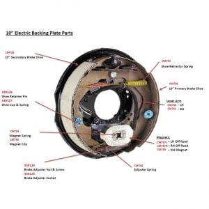 How to test electric trailer brakes
- Check the magnet arm for wear. Check for loose on the magnet arm post.
- Measure the voltage at the magnets with the car running.
- Pull the breakaway pin and measure the voltage at all magnets
- If less than 12v recharge breakaway or upsize cabling to magnets.
- Check for magnet wear inside the drum. The surface should be smooth.
- Install offroad magnets if magnet arms are worn.
- Measure lanyard pulls pin when chains are fully stretched.
- Easier to replace the whole backing plate than replace the parts.
You may be surprised that even auto electricians sometimes get caravan and camper trailer electric brakes wrong.
If there is a problem with electric brake magnets, the answer will likely be in the information below.
If you find a solution, please leave me a review comment below.
How to identify an electric magnet
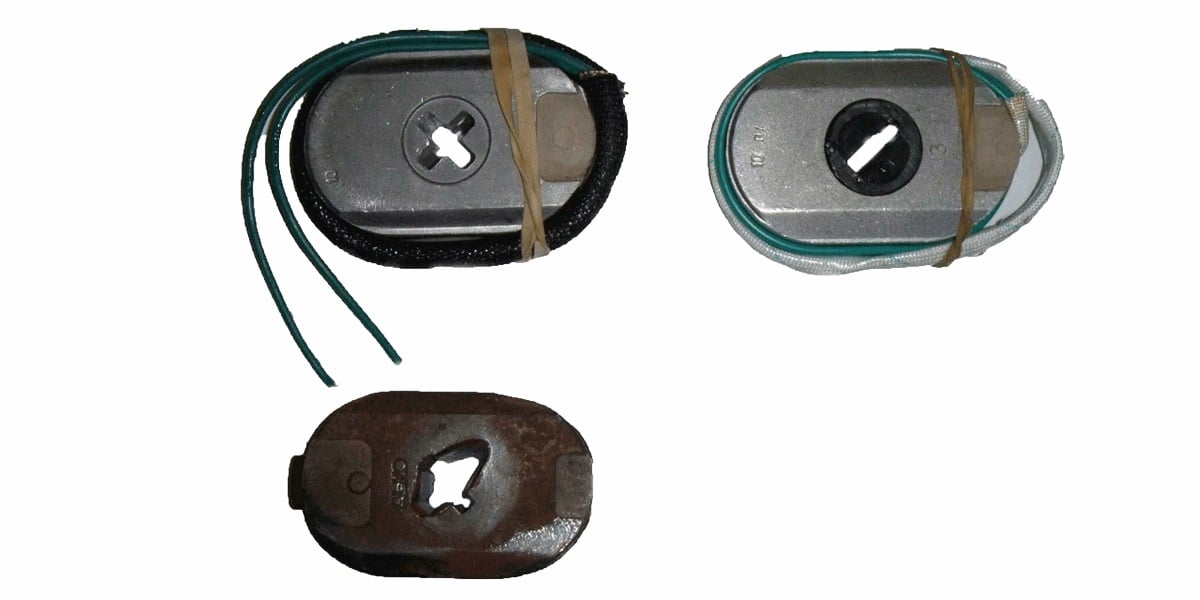
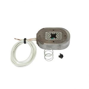
- Green cable leads identify a 10-inch standard electric and offroad magnet.
- White cable leads identify a 12-inch standard electric and offroad magnet.
- Black leads identify Dexter 10-inch and 12-inch magnets.
Electric brakes are a legal requirement for all trailers over 2000kg ATMs. Hydraulic disc brakes controlled by an electric brake controller are also acceptable.
A centre cross in the magnet’s middle identifies a standard electric magnet.
This type of magnet has copper 3mm green leads. The 3mm refers to the copper cross-sectional area. A 3mm external cable is used to join the tiny copper inside the bobbin or casing of the magnet.
To reduce voltage drop on cable runs to your brakes, select a 5mm cable if your cable run is less than 6 meters.
The gross trailer mass of your rig is the weight on the wheels when connected to your tow vehicle. Tandem axle brakes over 2000kg ATM require electrically activated brakes on both axles.
Cable Selection
When selecting the cable to wire your Caravan braking system, you need 5mm when running cable approx 6 meters or if you are using an automotive type cable, use 10m or larger.
Check this and insert 6.4 amps for two magnets and 6 meters of cable.
Finally, do not wire across the axle as this method requires more copper and creates copper losses and, therefore, more voltage loss. Wire the cable down inside each chassis rail. Drill a hole near the magnet tails and exit the frame rail with the supply cable.
Alternatively, if cabling is wired across the axle, increase the size of this cable to reduce voltage loss. If not wired correctly, the magnet at the end of the line will not brake correctly.
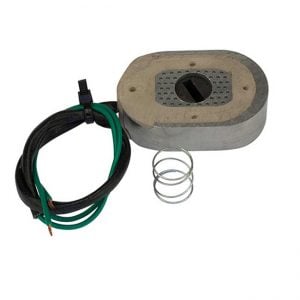 Al-ko Off-road Caravan Magnet Upgrades
Off-road magnets are essential when travelling on corrugated roads.
There is no retaining clip to hold magnets onto the magnet arm.
Al-ko recommends using a rubber band to temporarily retain the magnet in position until the 1st instance of braking releases the rubber band.
Consider a magnet upgrade before your trip to save the expense of brake failure on your outback trip.
A few other spare parts like bearings, grease, white spirits to clean parts, and a few extra wheel nuts are always handy spares.
Why dirt roads destroy standard electric magnets, click here.
Caravan Electric Brake Controllers
Most brake controllers will not give full voltage when stationary. They provide zero power when stationary if the brake controller has a proportional braking feature.
Use the manual feature on the brake controller when testing brakes.
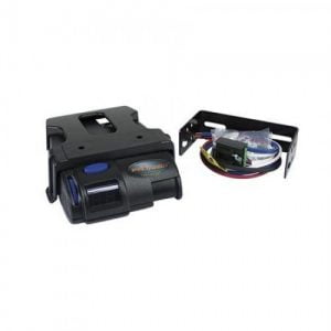
Advanced proportional braked controllers, such as the Tekonsha, use the trailer’s momentum or vehicle inertia to activate the trailer’s brake system.
A natural explanation may be to consider a pendulum inside the brake controller applies more voltage when the swing moves forward during braking.
When the vehicle is stationary, the voltage will be much less than 12v unless you have a dial resistor brake control unit. There can also be a time delay with some brake controllers.
The proportional control only works when your car is in motion, and your foot is on the brake pedal.
You may, of course, use manual control to activate your electric brakes. Pulling the pin on your breakaway switch will apply a brake force equal to full braking on your trailer’s brake.
Most importantly, the blue wire from the brake controller goes to the electricity backing plate.
Most brake controllers have reverse polarity protection. Chassis-mounted controllers do not usually have this protection. The brake controller may be fused and damaged if active and neutral are accidentally crossed.
Critical information on adjusting a Safety Switch Lanyard to the correct length.
Electric Magnets explained:
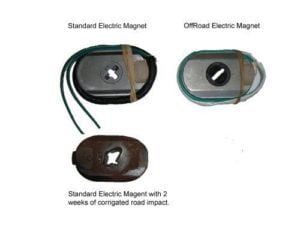
- Standard magnet. It uses a clip to hold it into position and a spring to press the magnet square into the drum surface when braking.
- The Al-ko off-road magnet has a spring but no clip. A rubber band has wrapped the magnet to keep it in place during assembly. The rubber band disintegrates upon the first application of the brakes.
- After two weeks on corrugated roads, a new magnet will require replacement. Vibrations have caused the metal tip of the magnet arm to cut through the electric magnet slowly. At this stage, the copper wire on the bobbin has been rendering the magnet non-functional. You can see an excellent reason to put off-road magnets on your rig.
Caravan electric magnets draw 3.2 amps @ 12v each.
(a) The big mistake when wiring electric brake magnets is to wire a 3mm cable down one side, then run more wire across the axle to the other magnet and connect.
Even manufacturers continue to make this mistake.
The long, additional run of the cable causes more voltage loss than is necessary.
(b) The correct method using a 6mm cable or larger is to run a wire down EACH chassis rail and connect each magnet independently. This type of connection reduces copper losses and the resulting voltage loss.
(c) Proportional-controlled electric brake controllers are most common in today’s market. The easiest way to explain proportional control is to think of a pendulum.
When your car is moving forward, the pendulum moves backward and forwards according to your vehicle’s inertia. The more braking you apply (pendulum moving forward), the more current is supplied to your brakes.
Confused want the correct cable size?
You will need the following.
- Distance from your car battery to your electric magnets.
- Amps per magnet.
- 6.4A @ 12v per side gives you around 6mm cable per side.
- If you run across the axle, then the equation is 12.8a @ 12v gives you a 12mm cable
I recommend running 2 x 6mm or 10B&S down each chassis rail for the best braking.
If you think that was good, please go to the bottom of this page and give us a rating, please.
Alternatively, contact steve.wotherspoon@couplemate.com.au if you require clarification.
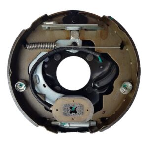
TIP: Having problems replacing magnets or brake shoes? Replace the whole electric backing plate for $93.67. Click the image on the right and buy.
Caravan Electric Magnets Not Working?
It is not unusual for your caravan electric brakes NOT TO WORK when stationary. Proportional brake controllers supply zero voltage whilst stationary. Activate the brakes manually when stationary.
I often get a call about uneven braking or one brake is stronger than the other backing plate.
Wiring magnets in series and using an undersized cable is the cause of the problem.
Wiring electric magnets with cable size of 6mm for the single axle (2 magnets) and 5mm for tandem axles. (4 magnets)
A voltage drop occurs when an insufficient cross-sectional area of copper causes the voltage problem of uneven braking.
Why is it so? I asked my Technical College Teacher
His reply was, “Voltage loss in the cable is inversely proportional to the size of the copper.”
His response tricked me at the time, so I studied harder.
I.e. the more copper, the less the energy loss.
If you are having problems with your brakes, it is most likely to be a cable problem.
Wire your brakes in parallel, not in series.
Connecting electric magnets directly to your tail light will cause severe voltage losses. Tail lights are designed to carry precisely 21w of DC. A set of 4 electric magnets draw 3.2 x 4 x 12 = 153.6 Watts under ideal conditions.
However, tail lights can be used as the control circuit in a relay to activate the electric braking system.
Can my electric brakes stop the caravan from swaying?
Yes, new technology can eliminate caravan sway. Visit this article to learn how to stop caravan sway.
Drum Brakes still not working?
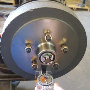 Here is a little-known cause of electric brake failure causing drums to become polarised from constant use and magnet scraping on the metal surface.
Your drums could be magnetised, repelling your magnets, thus causing ineffective braking.
If your magnets are drawing less than 3.2A each, there are two reasons
- Short circuit in your magnet
- The drum is repelling your magnet. Replace the drum.
Love to hear your comment if this solution fixes your problem.
Caravan Electric Brakes Tips:
- Adjust caravan electric brakes so the wheel spins between 1/2 and one turn.
- Brake shoes may be re-adjustment after the first 200km.
- Use a good brand electric backing plate. Not all backing plates are the same.
- Chinese bearings are often the cause of overheating brakes. Overheated brakes create a lot of dust inside your drum.
- Check out the price for replacing both backing plates as opposed to magnets and shoes. You could save a lot of pain by replacing the entire backing plate. Just a tiny tip many folks overlook.
- 12-inch electric magnets have a white coloured cable exiting the magnet body.
- Ensure that your lanyard cable on the breakaway switch is the correct length.
- Last tip, not all backing plates are the same. Al-ko and Couplemate make good backing plates you can trust, and yes, I am a little biased towards Couplemate products.
Mechanical Problems can also develop with caravan electric brakes.
- A loose magnet arm causes uneven wear on the magnet and loss of braking power.
- Shoes not aligned correctly generate heat.
- neven adjustment on the left and right shoes causes loss of braking power.
- Bearings are a significant cause of overheating. Chinese bearings may be the problem. Quality bearings have the words Japan written on both the cup and race.
- Here is a rare fault that causes ineffective braking. Constant use of drum brakes can cause the drum to become magnetised.
- Simply replacing the drum can fix this also.
Alko Off-road electric brake adjustment guide.
“Electric Brakes made Simple” is another electrical article by Steve Wotherspoon.
Finally, if you found this information helpful, please leave a review below.
* Life Time Guarantee on all Couplemate manufactured products provided those products are found to have been used according to the manufacturer’s product recommendations on our Terms and Conditions Page. If the product you purchased cannot be located in our trailer parts store, then the product is not manufactured by Couplemate Trailer Parts Pty Ltd and is not covered by Couplemate’s Life Time Guarantee.
© Steve Wotherspoon 24th March 2014
My electric brakes have stopped working, just been serviced, no faults showing on the Redarc Tow Pro.
What could my issue be?
I am taking back to the service agent on Thursday.
You have an open circuit on in your wiring. Your service agent will find it.
Steve, I am getting a constant reading of 5v on the blue wire from my Redarc basic controller when the footbrake is not engaged. Same reading at the magnets. Is this normal or is the controller possiblly faulty?
Hello Dave, all brake controllers voltage range should be between zero and 12v at the brake controller. When the foot pedal is not engaged the voltage is zero at the brake controller. If you are getting 5v at the brake controller then I suspect the controller is faulty. Your magnet voltage reading of 5v indicates there is no voltage loss caused by small wire size.
All very well explained. Thank you for the straight forward descriptions and no jargon
Great info – tks
I have an issue with the electric breaks on my van, even with the Redarc turned down to 2, when I break it’s as if the Redarc is fully on and there is a clunky noise at or around the vans tyres. Do I need a reset or an adjustment in the drum. Sorry if I’m not pacific enough.
Hello Paul, When parked, it sounds like the noise you are hearing is the magnet engaging the brake drum. The loudness of the engagement depends on the voltage applied. Measure the voltage output at various levels on the redarc. Thanks Steve Wotherspoon
Nice to read an article written by a professional who obviously knows their stuff – fabulous tech help, many thanks! Lots of detail no-one else gives!
5.”Check out the price for replacing both backing plates as opposed to magnets and shoes. You could have a whole lot of pain by replacing the entire backing plate. Just a small tip many folks overlook.” Steve I think you meant SAVE not have!
Hi ,
When you say-
Confused want the correct cable size?
You will need the following
Distance from your car battery to your electric magnets.
Amps per magnet.
6.4A @ 12v per side gives you around 6mm cable per side.
If you run across the axle, then the equation is 12.8a @ 12v gives you 12mm cable
My recommendation is to run 2 x 6mm down each chassis rail for the best braking.
DO you mean 6mm Automotive,which is 10B&S, which is 4.6mm Cross-sectional area ?
I am confused
Hello Alan, Sorry for the confusion, yes you are correct. 10B&S would be adequate to cover any voltage loss. Steve Wotherspoon
Nice article Steve, however, when you mention cable size, is it the diameter or the cross sectional area of the copper? When voltage drop is the issue the difference is important IMHO.
Cheers Bob
Brakes not Working
Voltage drop is caused by an insufficient cross-sectional area of copper that causes the voltage problem of uneven braking.
Copper in the cable is inversely proportional to the size of the copper. Ie the more copper, the less the voltage loss.
If you are having problems with your brakes, then it is most likely to be a cable problem.
I think you meant to say “Voltage loss” not “copper” in the cable is inversely proportional to the size of the copper.
If i adjust my brakes as in tip 1.
The brakes will apply when going over a bump.
They will apply harder when i am only lightly braking going down hill
Should tighten up until when doesn’t spin and back off 13 notches.
Apart from cable colour, what is the difference between 10″ and 12″ magnets? They appear to be the same physically and have the same current draw. Why are they not interchangeable………or are they?
Hello Bruce and thank you for your question,
There would appear to be little difference between these magnets. However, the 12″ magnet has more turns of copper on the internal spindle.
The difference in current draw is negligible (0.2a).
Are they really not interchangeable?
The 10″ magnet is rated to 800kg whereas the 12″ magnet is rated to 1250kg
If it was an emergency then I would swap them over and install the correct magnet at a more convenient time.
Current draw is a good indicator of correct size cabling. The specified current for magnets is 3.2a and 3.4a respectfully. If higher then full braking capacity cannot be achieved. Installing larger cable will reduce current draw to manufacturers specifications and optimum working conditions.
Thank you, Bruce
Steve Wotherspoon