
This is a general guide for converting an existing, unbraked axle into an electrically braked axle with hub drums. Installation procedures contained herein are to be completed by a suitably qualified person/s.
Caravan and trailer braking requirements are covered in ADR 38 (Trailer Braking Systems). Ensure you check local state regulations, as specifications can vary based on your trailer type, aggregate trailer mass (“ATM”), and other road-related requirements.
Moreover, electric trailers and caravan brakes require a brake controller to operate. The brake controller regulates the braking force applied to the trailer based on the tow vehicle’s braking. Depending on state regulations, this may be mounted externally on your chassis or installed internally in the tow vehicle.
Prior to Installation
This guide assumes your axle is bare, with no other brake fittings installed. If you have other fittings, such as caliper anchor plates, ensure these are removed before proceeding.
Moreover, please ensure all parts to be used are compatible with:
- Your bearing combination,
- Your stud pattern (PCD), and,
- Your wheel specifications (e.g. stud type).
Please ensure that all components are undamaged and free from debris. For help with trailer brake parts, please contact our team.
Installation Outline
- What tools/materials are required?
- What are the steps involved?
- Step 1: How to Prepare?
- Step 2: How to Position?
- Step 3: How to Weld?
- Step 4: How to Fit?
- Step 5: How to Wire?
- Step 6: How to Test?
- Step 7: How to Optimise?
Tools & Materials Required
Ensure you are familiar with the proper operating procedures and safety precautions, particularly with installation tools. It is the installer’s responsibility to be aware of all risks and to implement appropriate measures.
| Brake Components | Installation Tools | Measuring & Marking Devices |
* 3/8” (x10) for 12-inch brakes |
|
|
Step-by-Step Instructions
Step One: Preparing
Remove your axle from the underside of your caravan/trailer. We recommend placing it onto a welding table (or similar) for access during installation.
To do this, you’ll need to:
- Park the Trailer:
- Have your trailer or caravan parked on a flat, stable surface. Ensure the environment you’re working in is safe.
- Wheel chocks can be used to help prevent your wheels from rolling.
- Lift the Trailer:
- Use a jack to lift the trailer at the recommended jacking points (refer to the trailer manual for these).
- Once lifted, place jack stands under the trailer to keep it stable.
- Remove the Wheel & Hub Assembly:
- Follow the instructions here.
- Ensure you remove both the left and right assemblies.
- Loosen the U-Bolts:
- Your axle will be fastened to your leaf spring springs via a threaded U-Bolt Kit.
- Loosen nuts to remove the fish plate, washers, and U-bolts. Do this on both sides.
- You may choose to re-use your U-Bolts for reinstallation. If so, ensure to keep components in a safe place.
- Our team always recommends replacing U-bolts once unfastened.
- Detach Axle from Chassis:
- If your axle is mounted above your springs, you can simply slide it out from under your chassis.
- You may proceed to step two.
Take caution when loosening U-Bolts. Ensure you support the axle beam during this process, particularly if your springs are mounted above your axle (i.e. overslung).
How to Remove: Wheel & Hub Assembly
- Remove the Wheel:
- Using a lug wrench, loosen and remove your wheel nuts.
- Take off your wheel and set these aside.
- Remove the Hub Cap:
- Use a flathead screwdriver to gently pry off the cap in the centre of the hub.
- Remove the Cotter Pin:
- With the hub cap removed, you will see an axle nut secured with a cotter pin.
- Using pliers, straighten and pull out the cotter pin from the spindle.
- Remove the Spindle Hardware:
- Unscrew the spindle nut using a wrench or socket. Then, remove the washer located behind it.
- Keep both parts in a clean area for reassembly.
- Remove the Outer Bearing:
- Gently slide the hub forward to remove the outer bearing. Be careful, as the bearing may fall out as you remove the hub.
- Place the bearing in a safe, clean spot.
- i.e. Prevent dirt or debris from contaminating the tapered rollers.
- Remove the Hub:
- Once the outer bearing is removed, you should be able to pull the entire hub off the axle spindle. Take care not to damage the spindle upon removal of the hub.
- If the hub is stuck, lightly tap around the hub with a hammer to loosen it. Take care to not damage the hub or axle.
- (Opt.) Remove the Inner Bearing and Grease Seal:
- You can remove the inner bearing by prying out the grease seal at the back of the hub.
- Be careful not to damage the seal if you intend on keeping as a spare.
- You can remove the inner bearing by prying out the grease seal at the back of the hub.
Step Two: Positioning
- Identify the Weld Position:
- Locate where your weld rings (i.e. mount plates) are to be positioned.
- Use Figure 1 to identify where this position is relative to your bearing combination.
- For example, a Ford SL bearing combination will mark their welding position 129mm.
- Mark the Weld Position:
- Using a paint marker or etching device, mark where your weld rings are to be mounted.
- Repeat each side of the axle.
Step Three: Welding
This is a critical step. Weld rings that are mounted incorrectly will result in consistent braking issues. Refer the job to a qualified boilermaker if required.
Proceed with one of the installation methods below.
Method One: Workshop Installation
- Trial fit the supplied weld rings onto your axle at the appropriate measurement.
- Using magnetic clamps, ensure the plates are perfectly square and aligned at 90 degrees.
- Tac the weld rings onto the axle. Ensure you tac at the four corners of the weld ring
- Check alignment to ensure the weld ring is in the correct position.
- If correct, weld the remaining internal lengths of the weld rings around the axle.
- If not, cut your tac welds to remove the weld ring, realign, and repeat tac weld until correct.
Method Two: Field Installation
- Using the supplied studs and nuts, bolt your weld ring to the backing plate. Bolt securely but not firmly.
- Slide the bolted backing plate assembly onto the axle, stopping when the weld ring contacts the axle shoulder.
- Install the drum onto the axle, aligning the bearings on the journal, and tighten.
- Greased bearings not required at this stage.
- Adjust the backing plate so it is concentric with the drum.
- There should be about 5mm between the drum and the backing plate edge.
- Tighten the brake shoes so they press firmly against the inside drum surface. Tac weld the plate on the four corners
- Remove the drum, and weld the remaining internal lengths of the weld rings around the axle.
Step Four: Fitting
With the weld rings mounted, you can proceed with fitting the components. To do this, you’ll need to:
- Fit the Backing Plate:
- The backing plate houses your brake magnet and shoes (i.e. your braking mechanism).
- Follow the instructions here.
- Pack your Bearings:
- Pack both the inner and outer bearing with grease.
- Ensure you use grease that isn’t clay-based. Do not over-grease your bearings.
- Watch our YouTube Video on How to Properly Pack Bearings.
- Press the Bearing Cups:
- Gently press the inner and outer bearing cup into the drum.
- Take care to ensure cups are pressed evenly and firmly.
- You can use a bearing dolly to assist installation.
- Ensure cup surface is clean and free from dirt and/or debris.
- Position the Bearings and Drum:
- Place the greased inner bearing onto the axle spindle, followed by the outer.
- Slide the brake drum over the axle spindle.
- Ensure the taper roller bearings align with their corresponding cups.
- Press the grease seal into the hub.
- Install the Spindle Hardware:
- Add the flat washer and then the castle nut onto the spindle. Fasten the nut securely.
- Using pliers, add the cotter pin to secure the castle nut.
- Fit the Hub Cap:
- Fit dust caps into the drum.
- Ensure your cap is fitted firmly, securely, and not crooked.
- You can use a dust cap dolly to assist installation.
- Adjust the Brakes:
- With all items fitted onto the axle, you may now adjust the backing plate brakes.
- Follow the instructions here.
How to Install: Backing Plates
- Align with Weld Ring:
- With your weld ring mounted, slide the backing plate onto your axle and align the hole centres.
- Electric brakes include a left-hand and right-hand plate. Ensure the magnet faces away from the chassis and is situated at the bottom of the assembly.
- The shorter shoe typically faces forward (i.e. toward the trailer drawbar and tow vehicle).
- Fasten the Assembly:
- Using the provided hardware, securely fasten the electric brake assembly onto your axle.
- 10-inch systems use 4 x 7/16″ studs.
- 12-inch systems use 5 x 3/8″ studs.
- Using the provided hardware, securely fasten the electric brake assembly onto your axle.
How to Adjust: Electric Brakes
- Locate the Star Adjuster:
- On the back of the assembly, there will be small hole wherein you can access the star wheel adjuster.
- This star wheel allows you to adjust the brake shoes within the drum.
- Expand the Brake Shoes:
- Use a flathead screwdriver on the star wheel to expand the brake shoes (i.e. adjust them out).
- Expand the shoes until they are firmly pressed against the drum.
- You should be unable to rotate the drum when finished.
- Contract the Brake Shoes:
- Back off the star adjuster 10-13 clicks so the shoes contract.
- You’ll want to be able to spin the wheel hub freely with no drag.
- Back off the star adjuster 10-13 clicks so the shoes contract.
Step Five: Wiring
This is a critical step. Brake wire that is installed incorrectly will result in poor performing brakes (if at all). Refer the job to a qualified auto-electrician if required.
Brake magnets have two wires: one for power, one for ground. Using a standard 7-pin plug configuration, you’ll need to run two wires from the trailer plug: one from the Auxiliary Brake pin plug (5), and the other from Earth Return pin plug (3).
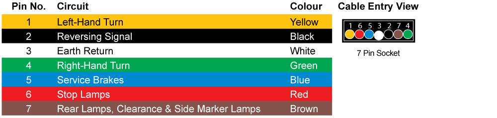
Magnet wires are not polarised, meaning that either wire can be used for power or ground. Some electric trailer brake systems may be wired in-series (i.e. wire running from one wheel to the other). However, Couplemate™ recommends wiring in-parallel (i.e. running seperate wires to each wheel).
Regardless, both magnet wires must be connected to close the circuit.
Step Six: Testing
- Connect the Trailer to the Tow Vehicle
- The 7-way trailer plug should be wired so that one of the pins is connected to the electric brake signal, which comes from the tow vehicle’s brake controller.
- Test Brake Operation: Hook up the trailer to the tow vehicle and test the electric brakes. You can do this by engaging the brake controller in the vehicle and ensuring the trailer brakes engage.
- Test the Breakaway Switch: Pull the pin on the breakaway switch to ensure the trailer brakes engage. This tests the emergency braking system.
How to Install: Final Safety Checks
- Ensure all wiring connections are secure and free of damage.
- Double-check the torque on the hub spindle nuts and lug nuts.
- Test the brakes on a low-speed drive, ensuring that they engage smoothly and adjust if necessary.
Step Seven: Optimising
Order Conversion Kit Online
Electric brake conversion kits are integral to the Couplemate™ Core range. Featuring our Australian-made brake drums, high-quality Japanese bearings, and our range of premium backing plates, our conversion kits are popular with Australian caravan and trailer owners.
For help with ordering parts, call us on 07 3348 3822, or reach out through our online form: Contact Our Team
0 Comments